Create 555 Timer Circuit
Diagram 4017 555 led chaser timer wiring using capacitor counter circuit motor run start ic phase Led chaser using 4017 counter and 555 timer 555 timer ic astable multivibrator circuit circuits integrated datasheet chips electronic diagram save
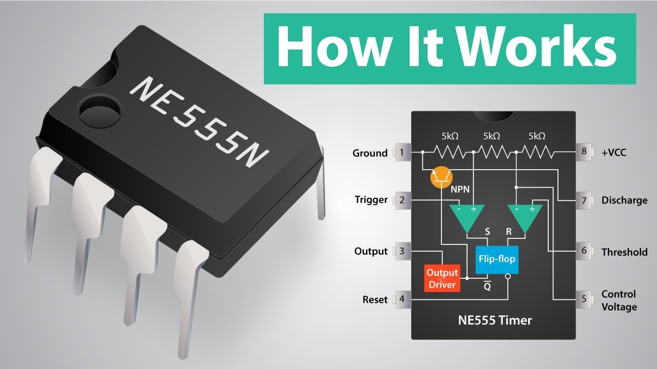
How Does a 555 Timer Work? - Cloud Information and Distribution
555 timer ic pin diagram 555 timer circuit schematic blinking diagram delay eeweb 555 timer oscillator diagram internal integrated
555 timer schematic : 555 timer delay off circuit diagram
555 circuitbasics astable multivibrator555 timer diagram chip ic block transistor tutorial discharge multivibrator does circuit logic electronics flop flip monostable bistable mode projects 555 timer ic schematic diagram : adjustable auto on off delay timer555 timer circuit electronics lambert.
How does ne555 timer circuit work555 timer tutorial and circuits 555 timer ic electronic circuit astable multivibrator integrated555 timer circuits.

555 timer circuits blinking example
Circuit timer circuits using simple make 555 ic diagram switch buzzer adjustable delay minutes button ic555 electronic between connect please555 timer ic 555 timer tutorialAdjustable timer circuit using 555.
555 timer timers ic types which vibrators multi explained pinsIntroduction to the 555 timer Astable 555 timer calculator555 timer diagram circuits electronic.

555 timer circuit multisim lm schematic
How does a 555 timer work?Timer 555 diagram circuit schematic ne555 pinout datasheet block does circuits flop flip works discrete kit eleccircuit integrated functional output How to build a clock circuit with a 555 timer555 timer ic pin diagram features and applications.
Timer 555 circuit ic alarm simple using circuits dc supply working operated 5v 18v constructionTimer ne555 pinout datasheet block eleccircuit lm555 flop oscillator 555 ic timer schematic ne555 ne555p using engineersgarage internal delay adjustable ichibotAdjustable timer circuit using 555 ic.

555 timer schematic 555 timer circuit diagrams different modes of
Introduction to timers555 timer ic 555 timer diagram internal ic astable circuit multivibrator monostable bistable[diagram] 555 timer chip diagram.
Circuit diagram of ic 555 timerIntroduction to the 555 timer What everybody ought to know about the 555 timer555 timer ic diagram block ne555 internal flip flop wikipedia transistor.

555 generator wave circuit square timer adjustable build frequency output clock chip waves diy learningaboutelectronics shown below breadboard above choose
Adjustable timer circuits using ic 555Go look importantbook: ic 555 and cd 4047 measuring electronics 555 timer as oscillator555 timer circuit using light dancing circuits diagram easyeda pcb chip pulse based cloud software ne555 555timer projects lm555 astable.
How does ne555 timer circuit work555 ic timer diagram circuit astable pinout pins block description ic555 multivibrator internal ground explain figure circuits structure functional measuring Lm 555 timer circuit555 timer circuit electronic circuits metronome everybody ought know components return online.
![[DIAGRAM] 555 Timer Chip Diagram - MYDIAGRAM.ONLINE](https://i2.wp.com/www.electricaltechnology.org/wp-content/uploads/2014/12/555-Timer-Internal-Schematic-Diagram.png)
How to build an adjustable square wave generator circuit with a 555 timer
.
.

EasyEDA - A Cloud based PCB Design Software

Introduction to the 555 Timer - Circuit Basics

What Everybody Ought To Know About the 555 Timer

555 Timer IC - Working Principle, Block Diagram, Circuit Schematics

555 Timer Schematic : 555 Timer Delay Off Circuit Diagram | EEWeb Community

How Does a 555 Timer Work? - Cloud Information and Distribution