Circuit Diagram Of 3 Bit Synchronous Counter
Counter synchronous flip jk flop bit using odd even numbers edge triggered negative logic digital electronics question stack form operation Up counter circuit diagram Synchronous counter circuit diagram
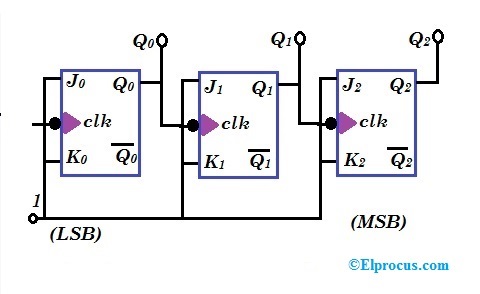
Synchronous Counter Circuit Diagram
4 bit up down counter circuit diagram 3-bit up-down synchronous counter 3 bit synchronous down counter
4 bit synchronous counter circuit diagram
17. the bcd (mod10) synchronous up counter circuit constructed with dDesign a 3-bit gray code counter using jk flip flops 2 bit synchronous counter circuit diagramBit synchronous equation flop using simplified geeksforgeeks input.
Synchronous circuit bcd mod10 flops constructed murat figSynchronous flop geeksforgeeks toggle 4 bit synchronous counter using jk flip flop verilog codeCounter circuit diagram.

3 bit asynchronous up counter with circuit diagram and truth table
4 bit synchronous counter circuit diagram3 bit synchronous counter truth table Digital logic3 bit counter circuit diagram.
4 bit up down counter circuit diagram3 bit synchronous counter using d flip flop [diagram] logic diagram of 3 bit synchronous counterWhat is synchronous counter? definition, circuit and operation of.

Counter bit synchronous down
Asynchronous 3-bit up down counter| electronics engineering study center4-bit asynchronous counter circuit diagram Introduction to countersCounter bit binary digital flip circuit using flops type.
[diagram] circuit diagram 3 bit synchronous binary counter[diagram] circuit diagram 3 bit synchronous binary counter Synchronous flop flops[diagram] logic diagram of 3 bit synchronous counter.
![[DIAGRAM] Circuit Diagram 3 Bit Synchronous Binary Counter - MYDIAGRAM](https://i2.wp.com/image1.slideserve.com/3085365/four-bit-asynchronous-binary-counter-and-its-timing-diagram-l.jpg)
Counter down bit asynchronous flip flop output
Synchronous binarySynchronous 3 bit up/down counter Synchronous counter : circuit, working, types & its applications4-bit synchronous binary counter.
Synchronous counters using jk flipflop3 bit binary up counter Electrical design a 3 bit up synchronous counter usinDesign a 3-bit synchronous binary counter.

Solved: refer to the 3-bit asynchronous ripple counter dia
Asynchronous decade counter circuit diagram .
.


Synchronous Counter Circuit Diagram

Design a 3-bit Gray Code Counter Using Jk Flip Flops - Worthy Knines
3 Bit Asynchronous Up Counter With Circuit Diagram And Truth Table

Electrical Design A 3 Bit Up Synchronous Counter Usin - vrogue.co

digital logic - Design a 3-bit up synchronous counter using JK flip

4 Bit Up Down Counter Circuit Diagram - vrogue.co

4 Bit Synchronous Counter Using Jk Flip Flop Verilog Code - Design Talk